Vintage MG Parts - Parts Site for the MMM Enthusiast
Richard's Pattern Making Blog - Machining
< Previous--¦--Page:- 1- 2- 3- 4- 5- -¦- Next > --
Day 22 - Tuesday, 25th June 2013:
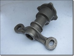 The sample casting with the flash removed and ready for machining.
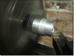 I am turning up a tailstock centre locator to support the nose of the casting as otherwise, with there being limited contact within the chuck, the casting will fly out as soon as machining of the body commences.
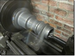 Next, a boring bar enters the front of the casting with the diameter machined to create a firm sleeve fit to the centre locator.
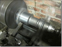 Now I can start machining the outer diameter of the body. A little precarious as the arms are spinning at speed which makes them almost invisible when working on other sections of the casting which iare not far away! Long reach cutting tools are used to create a safe clearance between the spinning arms and the tool post.
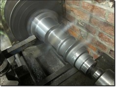 Change of cutting tools again and the flange is now machined
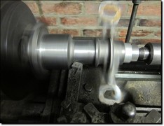 Change of cutting tool again to get into the left hand corner.
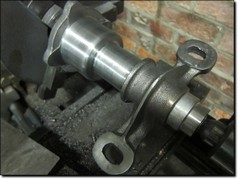 The next stage involves turning the casting around to drive it off the nose. The casting will need supporting on the main body section within a three point steady so that the spigot can be machined.
Unfortunately, it is at this point that I find that my three point steady has been misplaced in the property move so over the next week or so, I will be hunting this down so I can finish the job!
I will also shortly draw up a drilling jig which I will have laser cut out for the drilling of the holes in the flange. I will also show the jig being made.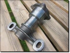 I have checked this sample casting for wall thickness and everything is as it should be. The core also has radiused corners internally for ultimate strength. I will say, there has been careful planning and this has so far turned out just how I had wanted.
But, would I change anything? Possibly yes, I amy slightly reduce the thickness of the flange on the pattern. The rear face is in the correct position so I will simply machine the pattern to the front of the flange face and then replace the raised bolt hole pads. I will also need to fill in the corresponding gap this will create on the red base section of the pattern. Both are a fairly quick straight forward task.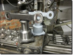 I have also decided that I will machine back the larger body diameter as during the foundry moulding process I highlighted that I can lose some extess iron and therefore speed up the machining time.
Note the edges of the 'eyes' on the casting. The foundry have caught the sand mould when it was being lifted off the pattern chipping the edges off the mould itself causing a slight loss of edge profile. They have since run off an additional sample which is reported as being fine although this casting has been good enough to proof the pattern and hopefully the machining process when we get there.
The foundry would ideally prefer the pattern to be converted to include having the pattern base mounted on a moulding board and for a core box to be created. This will involve making a fibre glass mould from the current pattern equipment so I may show this process a little later on in this blog. I do however need to concentrate on catching up with other general MMM parts orders.
When I find the three point steady in the next week or so, I will update the blog again. As the casting now stands however, it has turned out exactly how I had hoped in terms of its accurate detail, quality of the moulding process and the premium strength qualities of the casting itself.
This whole pattern making process may look straight forward enough through this photographic schedule although there has been considerable forward planning in this whole process, execution of correct principles for pattern making and of course, meticulous attention to detail in creating this latest Vintage MG Parts reproduction component. In terms of costs, this has mainly been my time investment whereby the pattern has taken around 25 hours to produce from start to finish. Material costs are fairly nominal.![]()
Day 23 - Saturday, 29th June 2013:
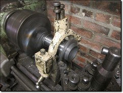 The casting is centred up in the chuck, being driven off its nose. A three point fixed steady is secured to the bed and adjusted up to the casting. This is needed as I am machining some some distance from the chuck and there is only 3/8th inch entering the chuck.
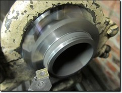 The first task in to face off the flange which you will not has already been done. I am now starting to machine the spigot.
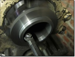 I am using an internal boring bar to clean up the bore of the casting as I am precission machining both sides of the spigot to create an accurate sleeve fit into the female spigot recess on the thrust plate.
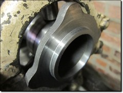 Apart from boring the bolt holes in the flange, this end is finished.
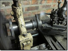 The casting is turned around and again supported in the three point steady. The excess section of the nose which was used to drive the casting is now machined away.
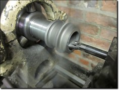 The bore is machined out further and to a depth of half an inch as a thick felt washer usually shrouds the supercharger drive shaft.
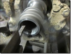 Lastly, a circlip groove is machined into the bore.
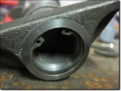 Circlip fitted.
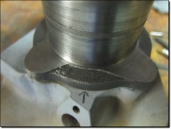 Next, I need to make sure that the radiator support arms are absolutely parallel with the dynamo shelf. I have therefore inserted a thrust plate into the bevel gear housing and then sat the engine mounting casting on top and at the correct position. Both the casting and thrust plate are marked up to each other.
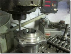 I need to make a drilling jig for the small production run I will shortly be doing but I have decided to use the thrust plate as a drilling guide for the first one and will then use the fully machined up casting to create the drilling jig which I may show on the blog in a few days.
The four holes in the flange are machined using a slot drill on the Bridgeport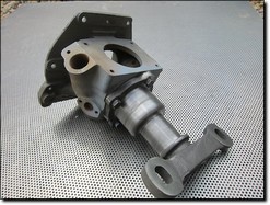 And here we are! One fully machined up C/J4 front engine mounting bracket.
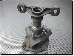
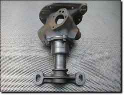
These will shortly be offered for sale within the website Parts Catalogue. We already had several orders prior to commencing this project and we are happy to add any additional expressions of interest to the list at this stage. I do however, intend for these to either be in stock or can be quickly machined up to order.
This more or less concludes this Blog in terms of creating a finished product from an initial idea. I do hope that I have managed to explain all the stages clearly and it has been a pleasure in providing all our website readers with an insight on how I tackle our various parts projects.
There have on average been around 200 daily visits to this Blog section since we commenced and I hope you have all enjoyed following my progress. If you would like to see more of these types of Blogs in the future then please let us know and we will have a think about the next suitable project to target.
I would like to thank everyone for their continued interest in this project.![]()
< Previous--¦--Page:- 1- 2- 3- 4- 5- -¦- Next > --