Vintage MG Parts - Parts Site for the MMM Enthusiast
The 'Volumex 7 Fin' Manifold - Start to Finish
;)
[Scroll down for more photographs]
Vintage MG Parts thought that some MMM enthusiasts might be interested in gaining an insight into how we go about producing a casting from an idea into a finished product. Pattern making is a process which few can fully appreciate as it is an operation that generally goes on behind the scene.
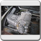
We have bowed to various customer requests to make a manifold for the Volumex which is purpose made for the Volumex set up on a MMM car. There are other similar products available but we have been specifically asked to make a lighter manifold with correct angles for our cars.
We hope the following points will prove interesting to inquisitive enthusiasts:
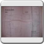
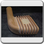
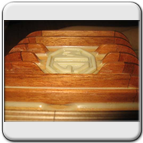
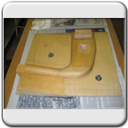
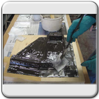
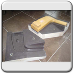
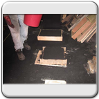
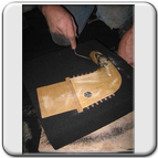
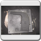
- We first made a thin plywood template of the plan view of the proposed course of the manifolds on the car. We then constructed a similar template to create the side profile including the inclined angle of the outlet pipe. The templates could then be used to assist in undertaking the scale engineering drawing to incorporate the correct angles and dimensions. The main body of the pattern was then constructed in hardwood sections.
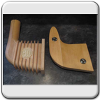
- The pattern is made in two halves with a central pattern "joint line". The joint line however will need to vary along the inclined outlet pipe section otherwise it will be impossible to extract the pattern from the sand during the foundry moulding process.
- An alternative way to tackle this varying joint line problem area would be to let the foundry moulder place a solid pattern (i.e. not a split pattern) half way in the sand and mould his own joint line. Unless you can find a highly skilled moulder, this generally leads to a messy joint line on the final casting which will need fettling afterwards and can leave an untidy result. It also increases the foundry moulding cost for each manifold. Making the "split pattern" is however, far more complex but creates a far neater end result.
- All patterns have to be made oversize to account for the contraction of the molten aluminium when it cools. This is known as the "contraction rate". Different metals contract at different rates so the dimensions of the pattern have to be specific to the casting material being used. Special contraction rules are used to transfer measurements from the engineering drawing to the wooden pattern making process.
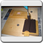
- The pattern has to be constructed with a "draft moulding taper" to all upright angles in order that it will draw out of the sand. This includes all sections of the cooling fins down to the pattern joint line.
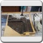
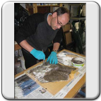
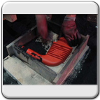
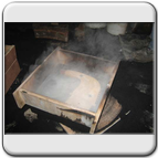
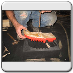
- Each half of the finned pattern will then be mounted on a "moulding board". In the foundry, the moulder will place a "moulding box" around the board with the pattern attached and then fill with sand which has a resin base and cures to make a strong sand mould. The process is then repeated for the other half of the pattern. The patterns are then extracted from the sand.
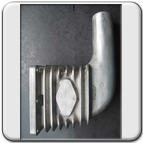
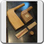
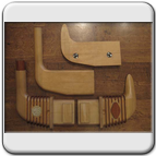
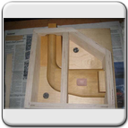
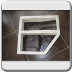
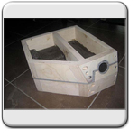
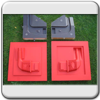
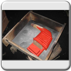
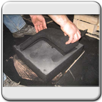
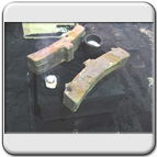
- The photos below also show the construction of a core box which is needed to make the "sand core". In its simplest terms, this is a mould made again in two halves as shown in our photographs. To make the mould, a wooden sand core profile is first made in two halves and with a stepped joint line. This will then be used to make the mould to then cast the sand core which will be carefully lifted from the core box when it is opened. The sand core will then be suspended throughout the void created by the finned manifold impression in the moulding box. Without a sand core inserted, we cannot create a hollow casting.
- The core must always be held centrally in position otherwise there will be thin sections to the casting wall. The wall thickness of this casting will be 6mm throughout. The main pattern therefore has core prints located at the end of the finned pattern (again, see attached photo) and the impression these create in the sand will form the anchor points for the sand core to firmly locate.
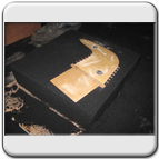
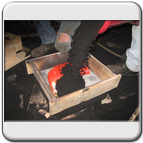
- Once the sand core is in place, the top half of the main mould is lifted back into place. A hole known as a "down gate" is created in the casting sand in order to let the molten aluminium flow into the pattern and around the sand core. We have chosen to use the flange as the entry point as we have a machining allowance surplus on the pattern and any trace of the "feed runner system" can then be machined off later.
We hope you have found this section of the site interesting. We attach a gallery of phographs below.
Click on an image below to view enlarged picture and a description of the process, click again (anywhere on screen) to close.
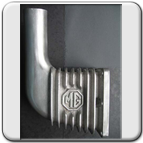
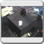
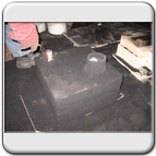
Design and pattern making:


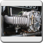
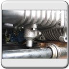
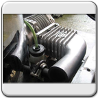
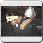
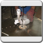
Foundry Process:


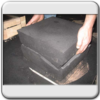

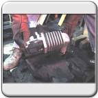


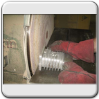
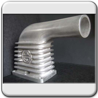
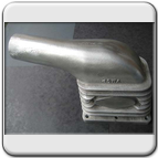
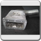
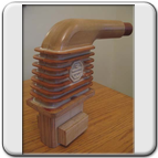
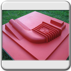
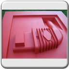
The finished 'Volumex 7 Fin' manifold: