Vintage MG Parts - Parts Site for the MMM Enthusiast
MMM Flywheel Lightening
During February 2010 we noted a posting on the MMM Forum regarding the various options which may be available to the MMM enthusiast when lightening the flywheel. Vintage MG Parts can now highlight the following article which offers excellent advice to reduce the weight of a P/L/K type flywheel to acceptable limits i.e. around 10 Ibs and can be equally useful for other MMM models.
Vintage MG Parts has been granted kind permission by Chris Leydon in the USA, to edit and publish online the article below. This is copyrighted and is not for reproduction of any sort without the prior express permission from the author via Vintage MG Parts.
We very much welcome receiving any similar technical articles which are thought to be of interest to the global MMM community.
![]()
Theory:
- The effort is to reduce not weight but the flywheel's moment of inertia: in this case, moment of rotational inertia.
- We suspect you all will remember Euler equations in calculus...well Euler was one of the first to develop the simple equation for rotational inertia: (mid 1700's)
--------------------![]()
- The flywheels resistance to your right foot (I) is not just a function of its mass (m), but also how far that mass is from its rotational center (r).
- So......the reason for trying to hollow out underneath the face plate and machining as much of the OD as practical was done in consideration to r squared above.
- And yes, a counterbalance crank will have more inertial mass simply because it is counterbalanced.
- However, there is an added loss in a the four cylinder bent wire crank in that it can never be in dynamic balance.
- The real question is: how much will you have reduced the moment of rotational inertia? Mmmmmm............!
Application:
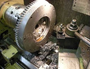
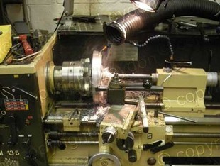
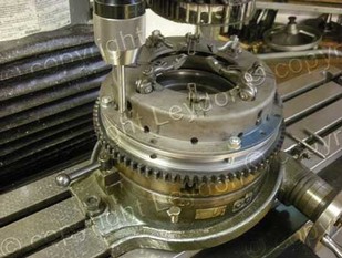
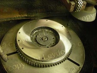
1.--Always use an adjustable chuck to center the flywheel on its original center.
2.--To fixture the flywheel, use an old crank flange. We use our own specially machined bolts to make them low profile as they protrude through the flywheel. (Otherwise standard bolts will interfere with your cutter shank)
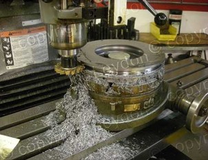
3.--Mount the flange normally. Run the lathe in normal direction CCW as seen from the bed, but mount your radiused cutter upside down, making sure to correct for the cutter being on centerline of the lathe. Set compound at 22 degrees and pocket out 2/3 the way to the clutch bolt holes. Make sure the finish is smooth. Keep 3/16" margin on the clutch surface face and bit off a set at the flywheel flange face.
 -----
----- -----
-----
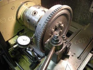
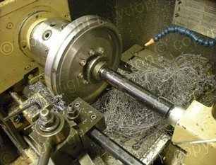
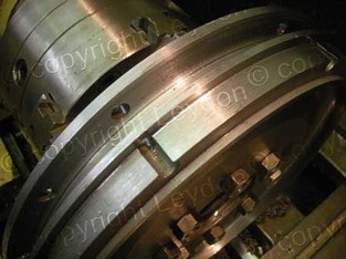
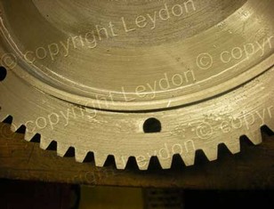
4.--Remount flywheel flange onto other side of flywheel. RECENTER WITH INDICATOR. Machine off ring gear
careful if using carbide because of the intermittent cut. We often set this up on a Bridgeport and mill rough mill first. Machine for the new ring gear allowing for a .020/.022" interference. You will notice that the ring gear will not fully engage if you go the original depth. We leave .050" proud and machine off the excess when shrunk on. We then make sure when assembling the starter that we adjust the starter bendix to be clear.....as you know MG had these spacer plates on some models....
 -----
-----
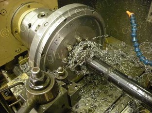
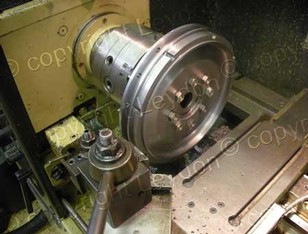
5.--Measure the clutch plate OD and machine the OD of the flywheel to suit. No sense in having more than is needed than to hold the clutch.
6.--Additionally, machine off the flange that captures the clutch bolt heads so there is only left what is needed.
 -----
-----
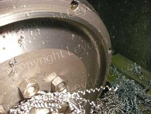
7.--I then machine a radiused trough between the clutch face and the flange left to locate the ring gear.
 -----
-----
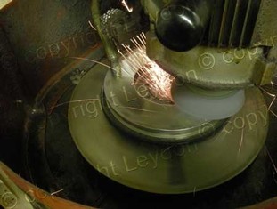
8.--After heat shrinking the ring gear in place, go back with an end mill and mill out the clutch bolt bores where the ring gear intersects with them, machine the ring gear on the one side and then mount on the flywheel grinder and machine the face.
-----
You are then left with a flywheel that is 10 pounds lighter, an engine that responds to instant acceleration without compromise to idle, and de-accelerates from 6800 rpm with reasonable speed for shifting and an entire garbage bin filled with cured metal shavings!!
Go to the top of page
Abbreviated Description:
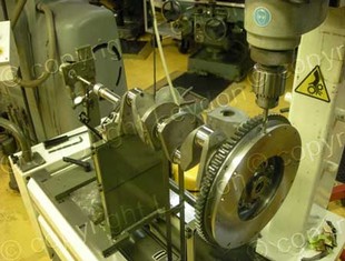
You can turn the flywheel as per the photos above, but a preferable way is to mill the outside diameter. This avoids the intermittent cut caused by the clutch bolt holes which wreaks havoc with the carbide tooling.
-
1.--The channel still should be radiused afterward.
 -----
-----
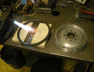
2.--It is only after all this work that the ring gear may be shrunk on. This is heated to 450 F, installed bevel facing clutch surface with an interference of .025"- .028"
-
3.--But when done, leave an inconvenient cord intersection in the clutch bolt holes.
-
4.--Centered back on the mill, these are milled out round again to provide bolt access.
-
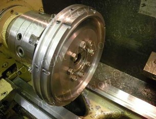
5.--At this stage, if one is using either the original clutch or a new diaphragm clutch, accurately center the housing on the flywheel and then spot drill and bore for pressed in hardened dowel pins.
-
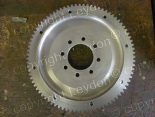
6.--So, finally the little beauty looks like this.
-
7.--But it ain't over yet. Surfacing can only be done after all of the above efforts as all the machining and ring gear pressing is sure to have created and relieved stress.......an the surface of the flywheel is sure to not have been great to begin with.
-
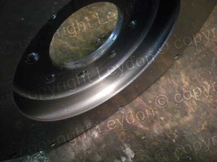
8.--It now looks like something more useable for the purpose.
-
9.--All the work has altered the balancing of the flywheel and it is not usable until it is rebalanced. First the crankshaft has to be balanced because this is used as a convenient mandrel for the flywheel. One has presumably removed the timing marks on the flywheel in the machine process, so it is good at this time to reinstall them.
-
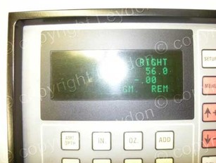
10.--The trough is a convenient place for removing weight for balance.
-
11.--And it IS possible to get it nearly perfect...This was done with a sensitivity of a half a gram / inch.
-
.... Happy milling!