Vintage MG Parts - Parts Site for the MMM Enthusiast
Richard's Pattern Making Blog
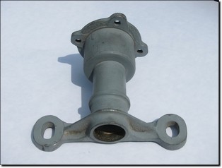
We have decided to manufacture our own C/J4 engine mounting/radiator support casting which are also used on supercharged P Types.
This pattern is going to prove interesting to make and we thought that enthusiasts may wish to keep logging on to observe our progress which we hope to deliver on a daily basis from an initial drawing through to a fully machined casting.
If blog watchers wish to comment or ask questions at any time along the way then please feel free to email and we will add these to this blog.
< Previous--¦--Page:- 1- 2- 3- 4- 5- -¦- Next > --
![]()
Day 1 - Monday, 27th May 2013:
 I have decided to manufacture this part in-house and the finished product will be added to our expanding parts inventory. This is going to be an interesting exercise for me and with some careful brainwork as my pattern making skills develop, I thought I would share the experience with you. Daily blogs will be shorter than this initial introduction which I hope will set the scene.
This part is to be cast in SG iron and the pattern will hopefully create a sand mould in two halves plus a sand core which is needed to create a hollow casting.
The problem as I see it, is that I cannot make a copy of the sample casting using a split pattern approach as there needs to be a 'split joint line'. This term refers to where the pattern will not easily draw out of the sand due to what is called 'under-cutting'. This is where the shape of the casting locks itself into the sand and prevents a neat draw from the sand. In addition, to draw a pattern out of the sand, all edge profiles must incorporate 'taper'. Five degrees minimum is a good rule to go by unless we are talking small measurements of say 1/8th inch.
I am therefore going to undertake what is called an 'odd-side' pattern making process. I will be making a solid pattern which will be half submerged into its own moulding board. The moulding board will follow a pre-determined split joint line around the pattern, i.e. the point where the casting will lift out of the sand. The pattern will therefore be half submerged into the moulding board.
Keep logging on over the next few days / weeks to keep up with progress whereby I will explain what I am doing as we are going along and hopefully all will become clearer as the project moves forward.
First stage, I am going to concentrate on making the pattern (as opposed to the moulding board). This will be a replica of the sample casting. The pattern will incorporate 'core prints' which will support the sand core later in the sand mould and which makes the casting hollow. As I will be casting in SG iron, I will loose 1 unit in every linear 96 in contraction as the iron cools. Put another way, for every linear 96.0 mm in length, I will loose 1.00mm. Therefore the pattern will be made oversize to compensate, using a pattern makers contraction rule. I will also be building the pattern up to add machining allowances to the finished raw casting.
Tomorrow, we will be producing a scale drawing for the main cylindrical body section of the pattern. This will be emailed to my father who will then immediately turn it up in pine on his woodworking lathe. Yellow pine comes from Canada and is kiln dried to remove all moisture. It is used specifically in the pattern making industry. I am not using my own lathe for this turning process as it is better to mess up my father's garage with wood turnings rather than dry my nicely oiled slides on my metalwork lathe with sawdust!
Let's hope this is going to all work out!
COMMENTS RECEIVED:
COMMENT: As a lapsed foundry metallurgist and also worker in my father's pattern making shop, I think you can use a stepped moulding board. This would put the body split along the mid point on a raised plinth on the cope and a sunken half on the drag, with the lugs on the board. How does that sound? (IB, 28/05/13)
RESPONSE: Many thanks IB. I think we are talking along the same lines and I may not have been too clear in my ramblings. However, I suspect there are several ways of tackling this and I will be interested to learn from you later on if you had what may transpire to be a different approach.
COMMENT: Looks interesting, Rich, even if I didn't really understand most of it! But as you say, hopefully it will all become clearer as time goes on. But it should give us an insight into just how much effort goes into making things that we often just take for granted when we see them for sale (and then moan about the price!). (SJ, 28/05/13)
RESPONSE: Thank you SJ. I am not a pattern maker by trade but always find pattern making projects fascinating providing a real mental challenge. MMM parts are generally not cheap therefore 'quality is king' as far as I am concerned.
![]()
Day 2 - Tuesday, 28th May 2013:
;) Tonight I am at the drawing board preparing a 1:1 scale drawing relating to the main body section of the pattern.
Tonight I am at the drawing board preparing a 1:1 scale drawing relating to the main body section of the pattern.
This will be emailed through shortly to my father who will tomorrow turn up the exact profile in yellow pine on his woodworking lathe. All being well, this will arrive back here in the evening and we can take a photograph and start thinking about adding additional timber components to build up the pattern.
Thank you for all the feedback and for the interesting comments on the forum...
Time for a beer
COMMENTS RECEIVED:
Thank you everyone for your kind emails of support. There are simply far too many to list tonight with the publicity that this blog is receiving.
![]()
Day 3 - Wednesday, 29th May 2013:
;) Today, the drawing was transferred to a wood turning. On the wider body diameter, there is a spigot. This is there to position a separate plate for the base of the casting. The reason this has been made as a separate part is to save trying to find a large piece of timber or laminate to then machine most of it away.
Today, the drawing was transferred to a wood turning. On the wider body diameter, there is a spigot. This is there to position a separate plate for the base of the casting. The reason this has been made as a separate part is to save trying to find a large piece of timber or laminate to then machine most of it away.
The extreme ends extend beyond the final length of the casting. These are core prints which will be used to locate the sand core later on.
;) Here it is, off the spindle and with the base plate a tight slide fit. This arrived back today and tomorrow we will start adding timber components.
Here it is, off the spindle and with the base plate a tight slide fit. This arrived back today and tomorrow we will start adding timber components.
![]()
Day 4 - Thursday, 30th May 2013:
;) The radiator shelf section is cut out on the bandsaw using thick pattern maker's grade birch plywood. For speed, I reduced the centre section on the Bridgeport milling machine.
The radiator shelf section is cut out on the bandsaw using thick pattern maker's grade birch plywood. For speed, I reduced the centre section on the Bridgeport milling machine.
;) An oversight... I should have incorporated the strengthening rib within the main body section. I have therefore, turned up a separate ring on the lathe. I have also removed a section of the main body to position the radiator shelf section.
An oversight... I should have incorporated the strengthening rib within the main body section. I have therefore, turned up a separate ring on the lathe. I have also removed a section of the main body to position the radiator shelf section.
![]()
Day 5 - Friday, 31st May 2013:
;) A long day at work usually deserves a feet up on a Friday night. Therefore, I have done little tonight but to sand profile the cross piece before wood gluing into position. The flange has also now been attached, making sure it is in exactly the right position. To achieve this, I have offered it up to a J Type front engine housing so we know that the rad shelf will be absolutely parallel with the machined dynamo mating face.
A long day at work usually deserves a feet up on a Friday night. Therefore, I have done little tonight but to sand profile the cross piece before wood gluing into position. The flange has also now been attached, making sure it is in exactly the right position. To achieve this, I have offered it up to a J Type front engine housing so we know that the rad shelf will be absolutely parallel with the machined dynamo mating face.;) Tomorrow is the weekend so inbetween machining of this week's general parts orders, I will be breaking off periodically to add to this pattern and there will be another website posting tomorrow showing more progress.
Tomorrow is the weekend so inbetween machining of this week's general parts orders, I will be breaking off periodically to add to this pattern and there will be another website posting tomorrow showing more progress.
It is interesting for us to note that this pattern making exercise has received more interest than we could have ever expected. Yesterday, Google Analytics recorded 742 website hits on this topic alone and today we are already close again. I will keep making progress.
Thank you for all your emails showing great interest in this blog. There is a lot more to come...
![]()
Day 6 - Saturday, 1st June 2013:
;) Today I intend to insert the infill sections and also create the centre rib.
Today I intend to insert the infill sections and also create the centre rib.
The quickest way is to revisit the drawing board and create the profiles on paper rather than shape small pieces by trial and error. I will therefore turn the drawing into small paper templates to then cut out sections of wood on the bandsaw and offer up.;) The infill sections are glued into position. I have then applied car body filler and will rub down before progressing with adding further pieces.
The infill sections are glued into position. I have then applied car body filler and will rub down before progressing with adding further pieces.;) The centre rib section is being built up in three sections. The gaps on the profile are fine as these will be lined with filler.
The centre rib section is being built up in three sections. The gaps on the profile are fine as these will be lined with filler.
The rib section by the way is also tapered so it will draw out of the sand.;) Note the top section of the rib curving around the body. This was the ring I machined up as shown a couple of days ago. I have simply used a partof it to form the centre rib section.
Note the top section of the rib curving around the body. This was the ring I machined up as shown a couple of days ago. I have simply used a partof it to form the centre rib section.
These rib sections are glued in place.;) More filler is applied.
More filler is applied.
I have machined out the eye holes on the radiator cross piece. I am intending these to form part of the casting, i.e. I do not wish to have to machine them in later as it is time consuming and unnecessary. However, it is a little tedious to machine oval holes which then need to incorporate taper. Later, I will therefore machine the holes oversize. I will replicate the hole profile in wood and with taper. This will be coated with release agent and positioned in the centre of each enlarged hole. I will then use a pattern making two pack fast setting resin to create the new hole profles within the pattern.
Tomorrow is Sunday and with a bit of luck we may finish this first part of the pattern.![]()
Day 7 - Sunday, 2nd June 2013:
;) One of the more laborious aspects is the tedious sanding down. A Dremel sanding tube removes the excess followed by sanding by hand.
One of the more laborious aspects is the tedious sanding down. A Dremel sanding tube removes the excess followed by sanding by hand.;) Pads are added to the flange.
Pads are added to the flange.;) Getting there. This part of the pattern has been made from 6 pieces of timber.
Getting there. This part of the pattern has been made from 6 pieces of timber.;) A diluted coat of cellulose based wood sealing solution is applied. It is then sanded using the lathe, minding the cross piece! The process is repeated again.
A diluted coat of cellulose based wood sealing solution is applied. It is then sanded using the lathe, minding the cross piece! The process is repeated again.;) A final coat of sealer is applied, allowed to dry and then polished with steel wool. Tomorrow evening, the pattern will be sprayed with primer. This allows any perfections to be highlighted.
A final coat of sealer is applied, allowed to dry and then polished with steel wool. Tomorrow evening, the pattern will be sprayed with primer. This allows any perfections to be highlighted.![]()
Day 8 - Monday, 3rd June 2013:
;) Limited time available tonight due to other VMGP work but here is tonights progress before the light goes. The pattern is sprayed in grey primer to identify surface imperfections, a few small dabs of filler and more rubbing down.
Limited time available tonight due to other VMGP work but here is tonights progress before the light goes. The pattern is sprayed in grey primer to identify surface imperfections, a few small dabs of filler and more rubbing down.;) Earlier, I mentioned about machining the eye holes over size. I have made a loose pattern with built in taper. This has been coated in release agent and secured to the underside of each pad with clamps. A quick set 2 pack pattern maker's resin is mixed and poured in. Seven minutes of curing time is all that is required. The loose pattern is then pushed out and the process repeated on the other side. The excess resin is then carefully sanded off. The result being, two identical eye holes with built in taper.
Earlier, I mentioned about machining the eye holes over size. I have made a loose pattern with built in taper. This has been coated in release agent and secured to the underside of each pad with clamps. A quick set 2 pack pattern maker's resin is mixed and poured in. Seven minutes of curing time is all that is required. The loose pattern is then pushed out and the process repeated on the other side. The excess resin is then carefully sanded off. The result being, two identical eye holes with built in taper.
The pattern is then sprayed with grey primer again and then polished with steel wool.;) Pattern part one is now finished.
Pattern part one is now finished.;) Tomorrow, I will be starting on the next stage which means building the base of the odd-side element of the pattern. This next process will be built up to the mid point along pattern one.
Tomorrow, I will be starting on the next stage which means building the base of the odd-side element of the pattern. This next process will be built up to the mid point along pattern one.![]()